
The Contractor’s Technical Proposal – Part 1
A typical bid (expression of interest) for construction works requires a contractor to demonstrate specific construction experience and financial muscle to start and complete a construction project. Specific construction experience can be demonstrated from a contractor’s past projects that have been completed or those that are ongoing.
A technical proposal supports (reinforces) the contractor’s claim that he is best suited to execute the construction works basing on past experience. It also assists the bid evaluators to determine beyond reasonable doubt that a contractor understands the scope of work involved and the requirements to complete the construction works on time.
In 2015, The Builders’ Garage was approached by a contractor to provide input to a technical proposal which was being prepared as part of a bid (expression of interest) to carry out construction works of a water supply and sanitation project. I have taken part in the evaluation of bids for construction works and I found this to be a very interesting request worth trying out. I personally took on this task.
In this article, I profile my personal experience preparing a technical proposal for a water supply and sanitation project, the challenges we encountered, how we overcame them and the lessons learnt thereafter.
1. My visit to the project site
After a lengthy discussion with the client, I visited the construction site and established;
- The availability and cost of construction materials and local labour.
- The proximity and availability of water and electricity to the construction sites. Most of the sites were adjacent to the national electricity grid but far away from the existing water supply system. This meant that piped water supply to the construction sites would be a challenge.
- The exact locations of the construction sites; the ground conditions at each site and the distances between each of the construction sites. Of particular interest to me was whether the construction sites could be accessed easily by vehicles or other construction equipment.
- The physical location of the sites in relation to the overall project area. This helped me determine an appropriate set up for the contractor’s site offices, the worker’s camp(s) and the deployment of key staff.
- The general security in and around the project area.
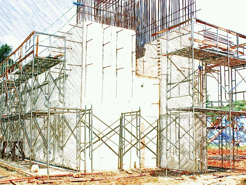
A number of pictures (images) like Figure 1 and Figure 2 were taken during this site visit and inserted into the technical proposal to provide objective evidence that the contractor had actually visited the proposed construction site, and that they appreciated the nature and complexity of the construction works envisaged.
In this particular case, it was obvious that the proposed construction site in Figure 1 predominantly had firm ground. In Figure 2, pointing out that some existing services like power lines would need to be relocated to pave way for construction works improved the quality of the technical proposal.

Figure 1: This photograph was taken at the proposed site for the water treatment plant
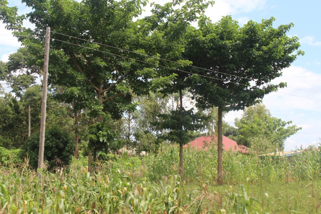
Figure 2: This photograph was taken at the proposed site for a new reservoir
On my way back from the site visit, I briefly scanned through the tender documents to get a feel of the site conditions and the scope of work involved. I communicated my immediate findings to the contractor. I was convinced that I would be able to produce a good technical proposal. What I actually didn’t realise is that I would have to use a lot of my own individual creativity to get the technical proposal done.
On my way back from the site visit, I briefly scanned through the tender documents to get a feel of the site conditions and the scope of work involved. I communicated my immediate findings to the contractor. I was convinced that I would be able to produce a good technical proposal. What I actually didn’t realise is that I would have to use a lot of my own individual creativity to get the technical proposal done.
2. Further familiarisation with the bid documents
Back at the office, I continued to familiarise myself with the tender documents. They comprised drawings, specifications, bills of quantities and the instructions to bidders (ITB). This tender was structured to the internationally recognised FIDIC conditions of contract.
In the instructions to bidders (ITB), I was majorly concerned with the minimum requirements for key personnel and construction equipment, the evaluation and qualification criteria and the scope of construction works to be undertaken.
For this project, the contractor was not permitted to propose and price alternative technical solutions for any part of the construction works. There were also some works to be carried out by third parties which could potentially have an impact on the contractor’s progress of work while on site. It was also indicated in the tender documents that the handover of certain key construction sites would be handed over about two to three months after the commencement date. The meant that the deployment of resources would have to be adjusted accordingly.
The specifications and bills of quantities enabled me comprehend in further detail the scope of work involved and the quality of work expected of the contractor. They also provided me with an opportunity to determine whether the entire scope of work (a simple sketch is shown in Figure 3) was consistent with the content in the drawings and bills of quantities. The drawings provided me with a pictorial impression of what the built up infrastructure would look like.
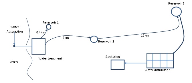
Figure 3: A general overview of the scope of construction works
3. Writing the technical proposal
- The site organisational setup
A site organisation setup is representative of the overall construction management structure which will be deployed by the contractor while on site.
Noticing that the scope of work would require different professional expertise, I decided that the work be split into packages. These were;
- Package 1 – Pipelines
- Package 2 – The Water Treatment Plant
- Package 3 – Reservoirs
- Package 4 – The booster station and associated electromechanical installations located at Reservoir 2.
- Package 5 – The sanitation component
My idea was that the work in each of these packages could be done concurrently (simultaneously) hence speeding up the construction work.
Mindful of the staggered site handover schedule proposed by the client and the client’s requirement to have a minimum of 13 key personnel deployed on site, I developed a personnel deployment schedule and a site organisation chart in line with the client’s requirements. The details comprised in the personnel deployment schedule were;
- The packages of work.
- The detailed scope of work under each package.
- The teams assigned to each package of work. For some packages of work like pipe works, two teams were assigned; each team working in a different geographical location of the site.
- The supervisors for each team. Depending on the volume of work (complexity) of each package, some packages had several teams and more than 1 supervisor (key staff) assigned to them.
A site organisation chart comprising all the personnel required by the client was developed. This represented the reporting hierarchy for all key personnel on site. It was further strengthened to include the contractual and communication linkages with the client’s project manager, the supervising consultant and external suppliers of materials. Another inclusion to the site organisation chart was a subcontractor who would be responsible for the erection of reservoirs.
I determined that since a number of the main project sites were quite some distance apart, two site camps would be set up by the contractor in order to effectively manage the construction works. The major site camp (camp site No.1) was situated at the site for the water treatment plant while the second camp site (camp site No.2) was situated at the third reservoir site. To ease coordination and communication, each working team within a specific work package was assigned a specific site camp.
Figure 4 and Figure 5 below represent the location of the major camp site (camp site No.1) and the supporting detail which was developed for it. These figures were inserted into the technical proposal.
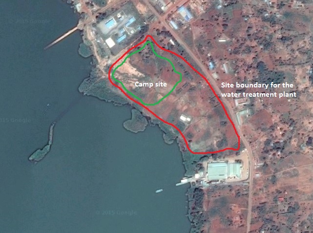
Figure 4: Camp site No. 1 – at the proposed site for the water treatment plant
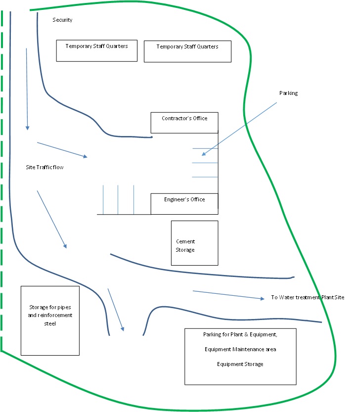
Figure 5: Further detail for camp site No. 1 located within the water treatment plant
……………Continue to part 2
2 Comments
Hello Eng. Am happy to see your technical proposal may you post some sample to email
Thanks
Peter, feel free to contact me via email at thebuildersgarage@gmail.com